Full Macropore Flow
1. Overview
The following description is based on Christiansen et al (2004).
Macropores are defined as a secondary, additional continuous pore domain in the unsaturated zone, besides the matrix pore domain representing the microporous bulk soil. Macropore flow is initiated when the capillary head in the micropore domain is higher than a threshold matrix pressure head, \(\psi_t\); corresponding to the minimum pore size that is considered as belonging to the macropore domain. Water flow in the macropores is assumed to be laminar and not influenced by capillarity, corresponding to gravitational flow. The vertical volumetric flux (positive upwards) qmp is then given by
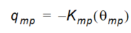
Equation 31.30
where \(K_{mp}(\theta_{mp})\) is the hydraulic conductivity of the macropores depending on the volumetric soil moisture content of the macropores, \(\theta_{mp}\). The continuity equation is expressed as
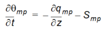
Equation 31.31
where Smp is a sink term for water exchange with the surrounding matrix. Combining (31.30) and (31.31) yields the governing equation for the macropores
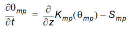
Equation 31.32
The term Smp becomes a source/sink term in Richards equation used in the matrix domain. This term is given by

Equation 31.33
where \(\psi_{mp}\) and \(\psi_{matrix}\) are the capillary heads in the macropores and in the matrix, respectively, and \(K(\theta_{matrix})\) is the hydraulic conductivity in the matrix depending on the volumetric soil moisture content of the matrix, \(\theta_{matrix}\). The exchange flow from matrix to macropore is only considered when the capillary head in the matrix, \(\psi_{matrix}\), exceeds the threshold pressure, \(\psi_t \cdot \beta_{mp}\) is a first-order linear water transfer coefficient, which is expected to increase with decreasing distance between macropores and with increasing hydraulic matrix-macropore contact. It can be expressed as
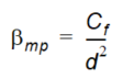
Equation 31.34
where d is an effective diffusion path length in metres. Cf is a dimensionless contact factor to take care of coatings on the interior walls of the macropores. Such a coating could be present due to, for example, root remnants, worm slime or mineral precipitation and can decrease the contact between matrix and macropore significantly. The contact factor ranges from 0.0 (no contact) to 1.0 (full contact).
Note
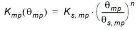
In MIKE SHE there are two values of \(\beta_{mp}\), depending on the direction of the flow into or out of the micropore. In the macropores, a simple power law function is assumed to represent the conductivity relation
Equation 31.35
where \(K_{s,mp}\) is the saturated hydraulic conductivity of the macropores, \(\theta_{s,mp}\) is the macroporosity, and n is an empirical exponent accounting for size distribution, tortuosity, and continuity of the macropores. n may vary from two to six, according to Jarvis (1994). The lower values represent soils of coarse structure with macropore networks of narrow pore size distribution and little tortuosity, whereas the higher values apply to soils with a wider macropore size distribution and larger tortuosity. If macropores are included in the simulation the hydraulic conductivity used to represent the soil matrix should exclude the effect of macropores.
The actual size, form and number of macropores are not explicitly considered in the model. Instead the macropore characteristics appear indirectly from \(\theta_{t,n}\) and \(\beta_{mp}\) that in the present formulation are dependent on soil type. The capillary pressure in the macropores, \(\psi_{mp}\), is supposed to vary linearly with the macropore moisture content \(\theta_{mp}\) between zero (at \(\theta_{mp}=\theta_{s,mp}\)) and \(psi_t\) (at \(\theta_{mp}=0\)). Neither root water uptake nor soil evaporation are considered to take place from the macropore domain.
The infiltration process description includes water entering the macropores, as well as the soil matrix at the soil surface. In this case, water is only ponded on the ground surface when the infiltration capacities of both pore regions are exceeded. Water flow into the macropores commences as the matrix infiltration capacity is surpassed.
The bottom boundary condition for flow in the macropores is a vertical flux at a unit hydraulic gradient. This flux is input to the saturated zone. A coupling of the saturated zone and the unsaturated zone is necessary when the groundwater level fluctuates. During groundwater rise, the water present in the macropores in the bottom unsaturated zone layer is released instantaneously to the groundwater and during groundwater decline, the macropores are exposed as empty.
2. Macropore flow solution method
The numerical formulation has to take into account the fact that flows in the macropore and in the matrix domains occur with significantly different velocities. Priority in development of the numerical scheme has been put on preserving the water balance and ensuring numerical stability at time steps that are not much lower than the time steps used in solving the matrix flow equation (Richards) alone. The solution method is mass conserving. The time step length is controlled by specifying certain limits for flow and exchange flow (depths) per time step, partly for ensuring correct dynamics of the macropore flow description and partly to avoid instability of the Richards solution due to high source/sink terms. The time step is controlled by performing an extra (a priori) macropore computation at the start of each matrix flow time step—with the matrix conditions from the previous time step. In case the resulting maximum (a priori) macropore flows, infiltrations, and exchange flows exceed the specified limits, a reduced time step is estimated, assuming linear relationship between time step length and flow volumes (unchanged flow rates). The procedure is repeated until the estimated maximum flows are within limits.
After the time step check, a normal time step simulation is performed, solving the Richards equation for the matrix flow—with reduced source/ sink terms from macropore-matrix exchange flows of the previous time step. After this the corresponding macropore time step is performed.
The calculation procedure consists of a double sweep algorithm with the following characteristics:
Downwards sweep (sweep 1)
First, a downwards sweep is performed, i.e. downwards flow from each cell to the cell below (or ground water table) in the macropore and in the matrix domains, and exchange flows, are calculated. Mass conservation is ensured by reducing the outflow from a cell if it exceeds the storage volume of that particular cell. The flow is not influenced by the water content of the receiving cell below, but the flow is set to 0 if the cell below has no macropores.
In the downwards sweep the downwards flow from a cell is calculated as the average of two estimates, and exchange flow as an average of four estimates:
- First, flow and exchange flow estimates are calculated as function of the macropore water content at the start of the time step. The estimates are reduced, if they exceed the start volume plus the inflow from the cell above.
- The second estimate is the flow and exchange flows as a function of the resulting macropore water content from the first estimate, including the inflow from the cell above (or the macropore infiltration if it is the upper cell). Again a reduction is made if the resulting volume would become negative.
- The final flow and exchange flow estimates are calculated as the average of the first two estimates. The flow is used as inflow to the cell below (or macropore recharge to groundwater if it is the lowest cell).
As mentioned above, each of the two macropore-matrix exchange flow estimates are calculated as two sub-estimates: The first estimate is calculated as function of the matrix water content at the start of the time step, and the second as function of the matrix water content as result of the first estimate. The same macropore water content (pressure) is used for both exchange estimates. Each sub-estimate is limited by two conditions:
- Flow from macropore to matrix is reduced if the resulting matrix water content would exceed saturation; and
- Flow from matrix to macropore is reduced if the resulting matrix pressure would be below the macropore pressure.
The macropore pressure used for exchange calculation is calculated as the macropore saturation (i.e. actual water content divided by porosity) multiplied by the cell height, and then reduced by the entry pressure. If the macropores of the cell are fully saturated, the macropore pressure of the cell above is added (hydrostatic conditions).
Upwards sweep (sweep 2)
In the second, upwards sweep, the macropore flows and the matrix-macropore exchange flows are reduced for situations where the macropores would otherwise become over-saturated. The resulting macropore water contents from downward sweep are checked, and when they exceed the macropore porosity the flow from the cell above and the exchange inflow from the matrix are reduced accordingly. If the cell receives exchange inflow from the matrix, the exchange flow and the flow from the cell above are reduced by the same proportion, otherwise only the flow from the cell above is reduced. Mass conservation is ensured by adding the flow reduction volume to the volume of the cell above (converted to water content).
The calculational time step is automatically adjusted in situations with high macropore and exchange flows so that these flows do not exceed certain limits, which from experience is known to generate numerical instability. In case of an increase of the ground water table, the water content in macropores now located below the groundwater table will be added to the groundwater recharge.
Note
Macropore porosity is added to the saturated water content to get the total porosity of the cell. This is important when adjusting the SZ-UZ exchange and the calculation of the relevant specific yield correction.
Note
The retention curve is only use for the matrix flow. It is not used for the macropore flow.
3. Verification of the Macropore Algorithm
Due to the complex flow description it was not possible to verify the code through tests against analytical solutions. Instead, several tests with different boundary conditions have indicated that the code is able to simulate the different aspects of the macropore flow events dynamically in accordance with the above theoretical basis. In addition, rigorous water balance tests have demonstrated that the continuity equation is simulated very well.
The numerical algorithm for the macropore component was previously tested by Thorsen et al. (1998). The only modification that has been made to the process descriptions since then is that the macroporosity that was described as a function of depth in the version used by Thorsen et al. (1998) now is described as a function of soil type.
An application of the macropore module is described in detail in Christiansen et al (2004).